Digital Tools At The Helm of Quantity Surveyors
By SJ Global Academy and Surbana Jurong’s Smart Cities Solutions
The Quantity Surveyor’s (QS) profession has come a long way from the card and shuffle days to using proprietary software that help in “taking off” (the measurement and description of the items required for a construction project) and bills of quantities. However, with the push of building information modelling (BIM), many things have changed both on the design and measurement aspects. Even visualisation is largely transformed, and gone were the days when we had to imagine how designs were like in 3D.
We can now visualise in 3D using several tools. This paper highlights some of these tools that the QS uses, which also paves way for new curriculum taught in institutes of higher learning (IHL). While necessary efforts were made to shed light on these tools, users are advised to test the tools out for themselves, speak to various vendors and derive their conclusion.
BIM Measurement
There are basically two types of BIM measurement tools in the market. The first is a standalone tool that would need the BIM model to be imported into their software or it works as a layer on top of the BIM model. Software like Glodon’s Cubicost (refer to Illustrations 1 and 2) and Cost X are appropriate for these tasks. The QS will need to have the technical competency to use such software as there are several levels to achieve. Some of these advance features include, but are not limited to, inbuilt formulas to help in calculating other materials that may not be shown in the model, such as formwork to the underside of beams and slabs.
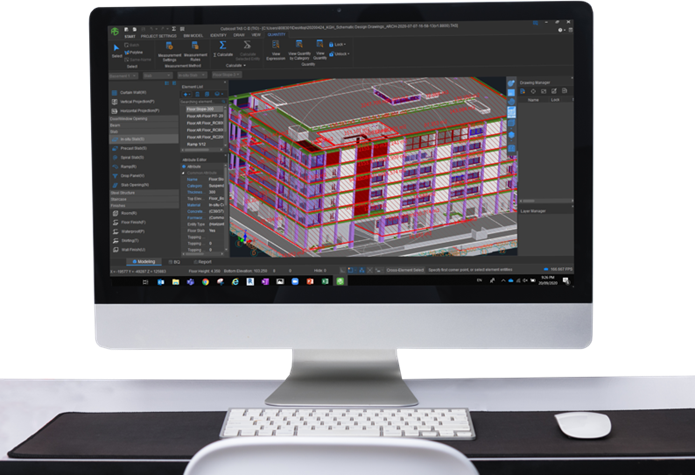 Illustration 1: Quantification from Revit Model using Cubicost
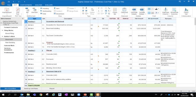 Illustration 2: A Cost Plan generated using Cubicost
The second type of software are the ones provided by BIM modeling tool vendors. For instance, Autodesk has provided the QS with Assemble (refer to Illustration 3) that assists in measurements directly from the BIM model. The QS will need to navigate in the various environments provided by the modeling tool vendors – such how one measures using a REVIT model (.rvt) versus an Open Building Model (.dgn).
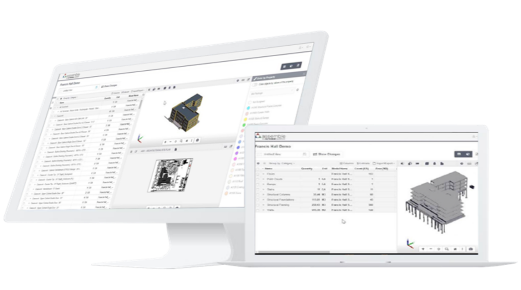 Illustration 3: A list view of Bill of Materials (BOM) using Assembly
Common Data Environments
There is a rise in the use of Common Data Environments (CDE) – a browser-based application that provides centralised storage, access, and sharing of all the data related to a construction project. It is rare that drawings are printed for the QS to measure now, especially with Integrated Digital Delivery (IDD) implemented in most larger projects. This means that the QS will need to navigate through the various CDEs (Refer to illustration 4) to obtain the BIM model. CDEs like “BIM 360 from Autodesk”, “Project Wise from Bentley Systems” and “BIM Cloud from Graphisoft”, provide a digital environment that allow users to navigate and store the files in the desired environment meant for their own projects and project teams.
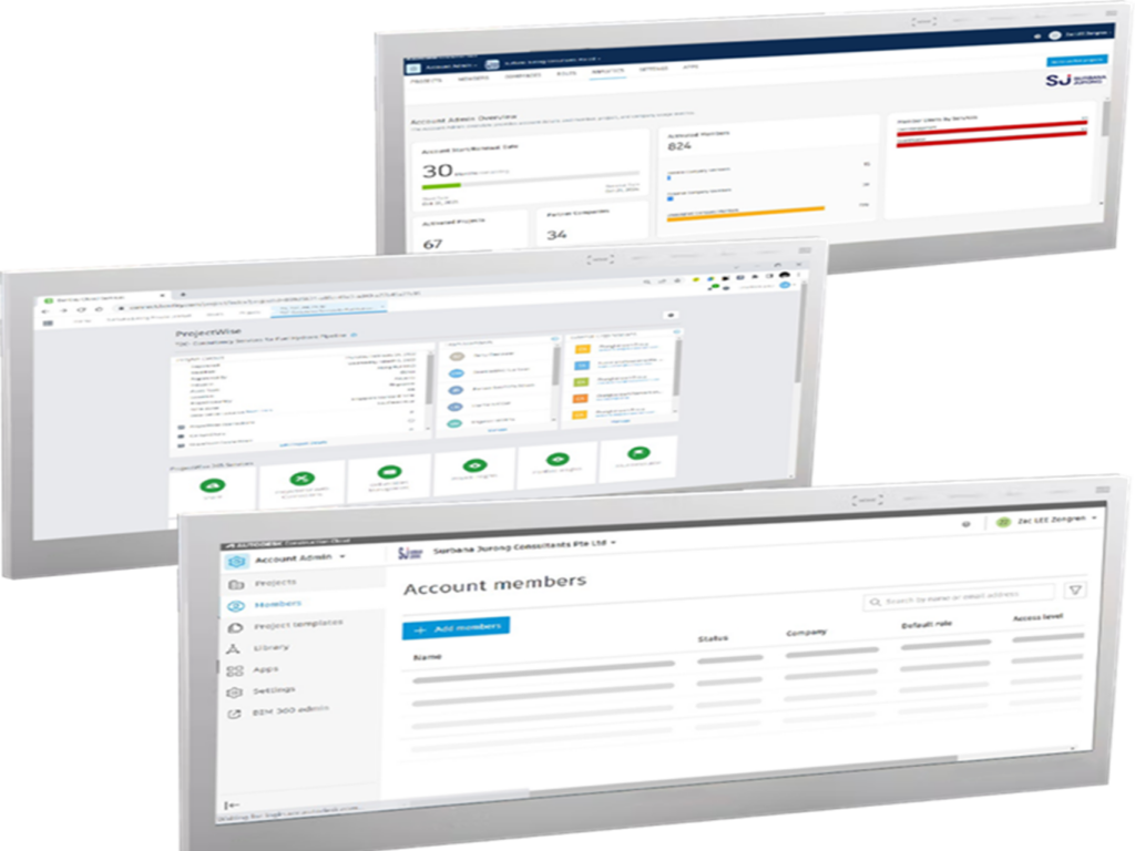 Illustration 4: Common Data Environments (CDE) – (top to bottom): BIM 360 from Autodesk / Project Wise from Bentley Systems / Autodesk Construction Cloud Page
With this, the QS needs to be proficient in the use of various CDEs specific to projects or agreed by the design consultants. The advantage of using a CDE, especially one that is certified under ISO 19650 (part 1 and 2) for BIM and Collaboration, is that the QS will be working on the right version of the BIM model from the onset.
It is good to ensure that there is a workflow for Integrated Concurrent Engineering and Design (ICED) within the design team. This means that when one model opens, specialists from the various disciplines (architects, engineers, etc) can work on this model and be immediately notified when there are changes. In the case of the QS, he uses the latest set of BIM models to measure from, instead of the traditional way where drawings were printed. This has proven to increase productivity as everyone is kept informed of the latest designs and intent.
Visualisation
The use of BIM means an increased opportunity in the use of Virtual Reality (VR) tools. VR tools can help the QS view the design so that it does not leave much to his imagination and quantity take offs clearly reflect the design and measurements. Such visualisation also helps in the provision and allowance for temporary works to be carried out, and estimators from both the consultants and contractors’ side can visualise the construction sequence. The intent of 4D BIM also allows teams to visualise the product before production begins. This approach enables efficient execution and lesser rework, which in turn generates time and cost savings for the project.
Such tools are powerful in that they help reduce the cost for safety, provides for temporary works and even allow for staging that are not reflected in the drawings. More forward-looking companies would employ Generative or Computational BIM to assist in their measurements, not only automating them but highlighting buildability, constructability, value engineering and even deriving construction methodologies.
There are several levels of visualisation. They range from looking at the 3D models on the screen, wearing goggles like the following:
- HTC VIVE (refer to Illustration 5);
- being immersive in a Computer Aided Virtual Environment (CAVE), and seeing the model on a smart board (refer to Illustrations 6 & 7);
- or seeing the model using a smart projector (refer to Illustration 8).
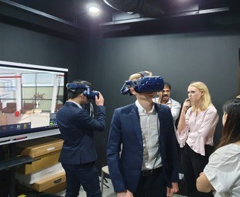 Illustration 5: Be visually, physically and emotionally amazed by new virtual worlds with HTC VIVE
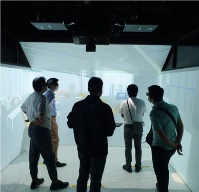 Illustration 6: Being immersive in a Computer Aided Virtual Environment (CAVE)
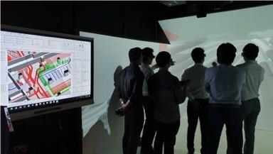 Illustration 7: Reflecting the model on a smart board
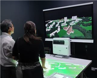 Illustration 8: Seeing the model using a smart projector
These systems have their pros and cons, and comes at different capital and operational cost. The QS firm would choose what is best suited for the business. One thing that is certain; it beats the ambiguity of trying to “imagine” how the design would look like.
Digital Tools and Imagin
The QS can also use drones and photogrammetry (refer to Illustrations 9-11) to aid in the measurement of large areas, such as sand needed for reclamation or simply to get data for interim project payment. With the current use of 4G, the QS drone pilot will need to have the line of sight (LOS) to carry out missions. With the dawn of 5G, one can even fly the drone from the comforts of the site office “Beyond Visual LOS (or BVLOS). There is also the possibility of using robots to gather data for the QS who is in the Facilities Management trade, and require measurement details for maintenance, repair and operational needs.
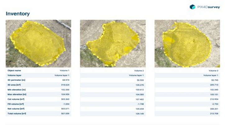 Illustration 9: Inventory management for stockpile using drone and photogrammetry measurement. Here, control points are used to ensure high accuracy
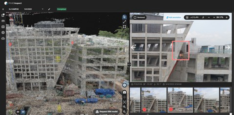 Illustration 10: Pointclouds generated from photogrammetry, which can be traced back to the contributing images for higher clarity
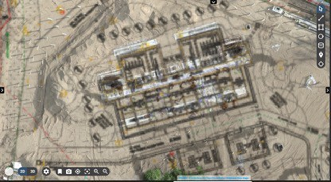 Illustration 11: Drone and photogrammetry are able to capture and generate site condition rapidly and cheaply. Orthoimages above show an example on work-done vs design plan, which can be used to track on-site assets from a bird’s-eye view.
Sustainability
Apart from the QS measurement, working in a CDE and being able to visualise, there is also a need to be able to use the native BIM files itself, such as write plug ins and sort instructions for the programme. The QS can also interrogate the BIM model and put in CO2e values in the model to come up with the total tonnage of embodied Carbon in the build. He can then understand how much recyclable materials are in the building. He is also able to measure the waste of the building, and even carry out costing for deconstruction in the future.
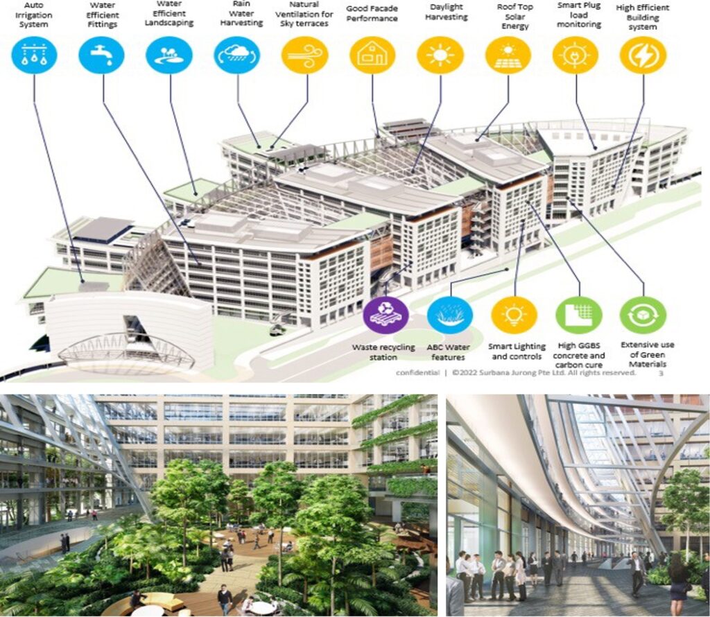 The QS will need to be aligned with new sustainable designs, smart trends and products used, such as the ones in the new SJ Campus
Conclusion
The above briefly describes the tools that Quantity Surveyors can use in the digital era, and in Integrated Digital Delivery. There are also other management and procedural aspects that the QS needs to be proficient in, such as the ability to participate and follow the BIM Execution Plan (BEP), and encourage designers to follow a certain methodology to model after BIM.
After all, stakeholders of the project would want to achieve a common outcome – to be able to work effectively on a single platform, and at the same time, being cost and time efficient.


